Flood Warning System (collaboration) Measuring Device: Manuel Rueda, Programming: Kelly Nichols

As part of a collaborative project focused on flood warning systems, this proposal was geared towards populations residing in flood-sensitive zones along The Senegal River where our proposed measuring devices would be deployed. I suggested to provide an LED display that would respond to data collected by the measuring devices and that would warn the public of water levels on a blue, yellow, and red scale. The LEDs served to respond to rates of illiteracy amongst Senegalese communities to allow a certain universality for displaying data. In this prototype, I focused on creating a low-cost tool that could include a “Self Sufficient Arduino Board” (as found on www.instructables.com) using a diode, a rechargeable 9Volt battery and connected to solar panels placed along the surface of the display’s encasing. To demonstrate the functionalities of this display, I wrote a code that simulates how one would see the changes in water levels at different geo-points, through the changes in LED scales.
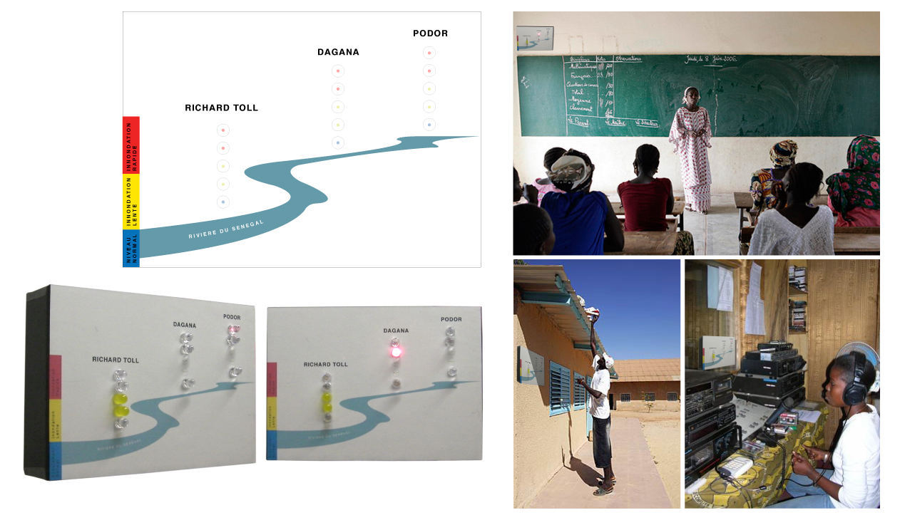
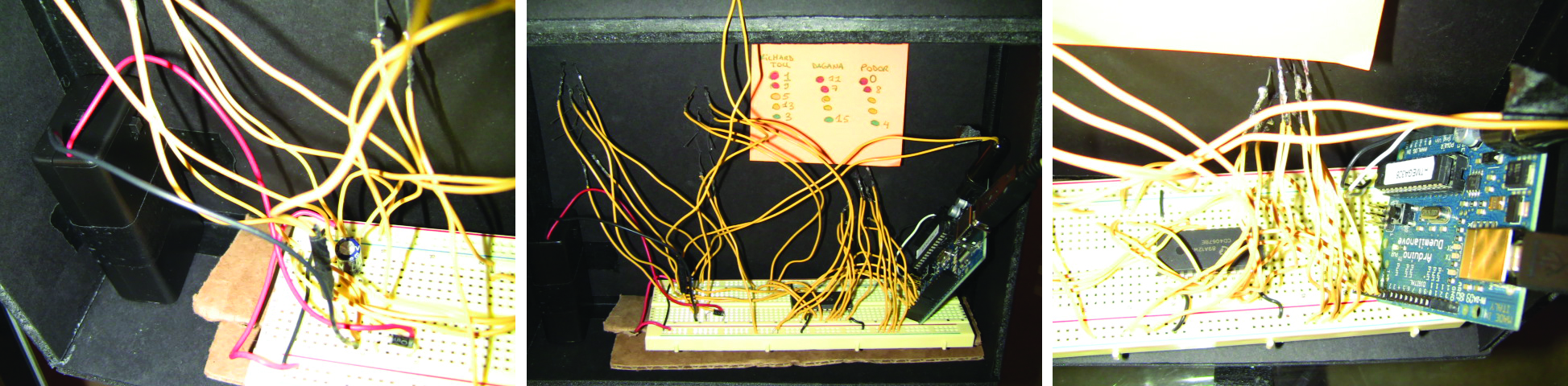
Prototype: LED display and circuit using a CD4067B multiplexer

Arduino Code // modified by Nour Diab Yunes // February 2010 /* Multiplexer output example Controls 16 outputs, one at a time, using a CD4067B multiplexer. This sketch loops over the 16 channels of a CD4067 multiplexer, switching the input to each output channel in turn. It then fades up and down the input channel using analogWrite(). The circuit: * CD4067 multiplexer attached as follows: – address pin A: digital I/O 2 – address pin B: digital I/O 3 – address pin C: digital I/O 4 – address pin D: digital I/O 5 – input pin: digital I/O pin 6 – LEDs attached from each of the CD4067’s output channels to ground created 21 May 2009 by Tom Igoe http://www.tigoe.net/pcomp/code/category/arduinowiring/540 for more */ // put the address pin numbers in an array // so they’re easier to iterate over: const int channel[] = { 2, 3, 4, 5}; // the output pin channel (mux’s input): const int outputPin = 6; // int declaring array muxWrite1 // sequence row: richardToll int muxWrite1[5] = {3, 13, 5, 9, 1}; int muxWrite2[3] = {4, 7, 11}; // sequence demonstration //int muxWrite2[3] = {0, 7, 8}; void setup() { // set up all pins as output: Serial.begin(9600); for (int thisPin = 2; thisPin < 7; thisPin++) { pinMode(thisPin, OUTPUT); } } void loop() { int i; for (int i = 0; i < 3; i = i + 1) { //Serial.println(muxWrite2[i]); muxWrite(muxWrite2[i]); analogWrite(outputPin, 255); delay(800); } int j; for (int j = 0; j < 5; j = j + 1) { Serial.println(muxWrite1[j]); muxWrite(muxWrite1[j]); analogWrite(outputPin, 255); delay(800); } } void lightLED(int index) { muxWrite(index); analogWrite(outputPin, 255); } void muxWrite(int whichChannel) { // iterate over the number of pins you’re using: for (int thisPin = 0; thisPin < 4; thisPin++) { // calculate the state of this pin based on // its bit value in whichChannel: int pinState = bitRead(whichChannel, thisPin); // turn the pin on or off: digitalWrite(channel[thisPin],pinState); } delay(5); }


