This concept aims at providing users with a new way of perceiving and thinking of structures and patterns in the world, and reconsidering the way they interact with ‘the social.’
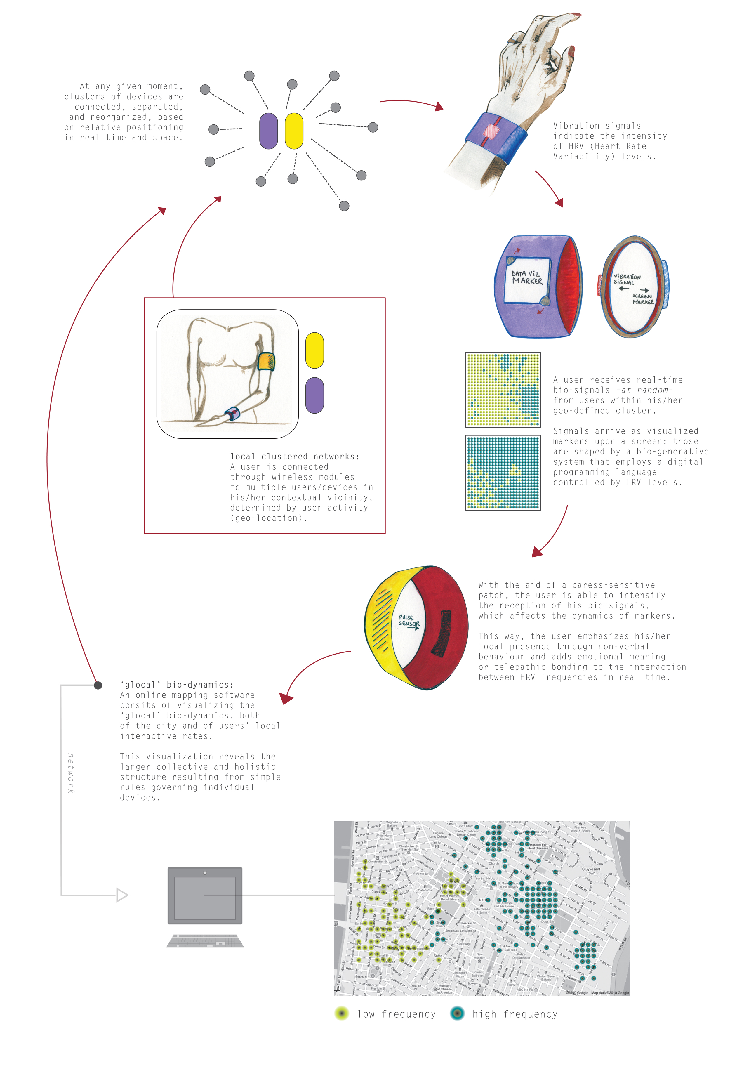
Through monitoring users’ HRV (Heart Rate Variability) levels, devices will enable individual devices to send bio-sensitive markers to neighboring users -at random-, relying closely on relative positioning in real space and time.
Markers will consist of mathematically generated visuals responding to intra-personal electrical impulses (biofeedback), revealing a certain type of emotional state, giving new content to space and new meaning to ‘communication.’ In this way, users will interact with one another on anonymous grounds and on nonverbal and non-invasive communication levels. Devices will also allow users to visualize bio-interactive spaces, and decipher the larger-scale structure of hidden bio- dynamics in the context of new local interactivity in habitual contexts.
The following prototype is an exploration of biofeedback and how we can translate neglected and invisible data into meaningful and highly visible language onto a screen.
I have used a light-to-frequency converter module to read pulse rates. A light-to-frequency converter calculates the sensitivity of the light passing through your finger and converts these values into frequencies or pulsations. I have also used a stretch sensor that, as the guide describes, changes resistance as it stretches. By stretching the object, users employ a new behavior language for changing and communicating new visual results on the screen.

Prototype: paper wristband using a Lilypad Arduino, a TLS230R light-to-frequency

Arduino Code
// http://home.teampaulc.org/arduino/tsl230r-to-arduino-interface /* * reads TLS230R module * sends to serial monitor */ const int ledPin = 8; // led connected to digital pin 8 // setup the TLS230R to Arduino mapping #define TSL_FREQ_PIN 2 // output use digital pin2 for interrupt #define TSL_S0 3 #define TSL_S1 4 #define TSL_S2 5 #define TSL_S3 6 #define READ_TM 1000 // milliseconds between frequency calculations // you do not need to define analog pins int calcSensitivity; unsigned long sensitivityHighThresh = 2000; unsigned long sensitivityLowThresh = 100000; unsigned long pulseCount = 0; unsigned long currentTime = millis(); unsigned long startTime = currentTime; unsigned int tm_diff = 0; // freq will be modified by the interrupt handler so needs to be volatile // freq holds the latest frequency calculation unsigned long frequency; float uWattCm2; volatile unsigned long curPulseCount; unsigned int count = 0; unsigned int scale; // holds the TLS scale value, see below int ledState = LOW; void setup() { pinMode(ledPin, OUTPUT); // declare the ledPin as an OUTPUT Serial.begin(57600); sensitivity(1); Serial.println(calcSensitivity, DEC); // attach interrupt to pin2, send output pin of TSL230R to arduino 2 // call handler on each rising pulse attachInterrupt(0, add_pulse, RISING); pinMode(TSL_FREQ_PIN, INPUT); pinMode(TSL_S0, OUTPUT); pinMode(TSL_S1, OUTPUT); pinMode(TSL_S2, OUTPUT); pinMode(TSL_S3, OUTPUT); digitalWrite(TSL_S2, HIGH); // S2 and S3 HIGH = 100 output scaling digitalWrite(TSL_S3, HIGH); scale = 100; // set this to match TSL_S2 and TSL_S3 } void loop() { float stretchSensor = analogRead(2); Serial.println(stretchSensor); Serial.println(pulseCount); setSensitivity(); delay(10); // if the sensor reading is greater than threshold: // if (frequency >= threshold) { // // toggle the status of the ledPin: // ledState = !ledState; // // update the LED pin itself: // digitalWrite (ledPin, !ledState); // // send the string “Pulse!” back to the computer, followed by newline // Serial.println(“I am reading your pulse!”); // } // this is just for debugging // it shows that you can sample freq whenever you need it // even though it is calculated once a second // I am dislplaying it every 2 seconds // note that the first time that freq is calculated, it is bogus // count++; //Serial.print(count); //Serial.print(“tuW/cm: “); //Serial.println(getUwattCm2()); } void add_pulse() { // increase pulse count pulseCount++; // DON’T calculate the frequency every READ_TM ms // just store the pulse count to be used outside of the interrupt currentTime = millis(); if( currentTime – startTime >= READ_TM ) { curPulseCount = pulseCount; // use curPulseCount for calculating freq/uW pulseCount = 0; startTime = millis(); } } long getUwattCm2() { // copy pulse counter and multiply. // the multiplication is necessary for the current // frequency scaling level. frequency = curPulseCount * scale; // get uW observed – assume 640nm wavelength // calc_sensitivity is our divide-by to map to a given signal strength // for a given sensitivity (each level of greater sensitivity reduces the signal // (uW) by a factor of 10) float uw_cm2 = (float) frequency / (float) calcSensitivity; // extrapolate into entire cm2 area uWattCm2 = uw_cm2 * ( (float) 1 / (float) 0.0136 ); return(uWattCm2); } void setSensitivity() { getUwattCm2(); if (uWattCm2 < sensitivityHighThresh) { sensitivity(3); return; } if (uWattCm2 > sensitivityLowThresh ) { sensitivity(1); return; } sensitivity(2); } void sensitivity(uint8_t level) { switch (level) { case 1: if (calcSensitivity != 10) { //Serial.println(“Now at low sensitivity.”); } digitalWrite(TSL_S0, HIGH); // S0 HIGH and S1 LOW = 1x sensitivity digitalWrite(TSL_S1, LOW); calcSensitivity = 10; break; case 2: if (calcSensitivity != 100) { //Serial.println(“Now at mediUm sensitivity.”); } digitalWrite(TSL_S0, LOW); // S0 LOW and S1 HIGH = 10x sensitivity digitalWrite(TSL_S1, HIGH); calcSensitivity = 100; break; case 3: if (calcSensitivity != 1000) { //Serial.println(“Now at high sensitivity.”); } digitalWrite(TSL_S0, HIGH); // S0 HIGH and S1 HIGH = 100x sensitivity digitalWrite(TSL_S1, HIGH); calcSensitivity = 1000; break; } return; }
Processing Code
// modifed by Nour Diab Yunes, May 2010 // “Textures” code created by Lev Kanter, 2008 /** * Simple Read * * Read data from the serial port and change the color of a rectangle * when a switch connected to a Wiring or Arduino board is pressed and released. * This example works with the Wiring / Arduino program that follows below. */ import processing.serial.*; Serial myPort; // Create object from Serial class int pulseCount; // Data received from the serial port int stretchSensor; // analog variable // http://processing.org/learning/basics/noise2d.html float inc = .06; int density = 4; float znoise = 0.0; void setup() { size(500, 500); // I know that the first port in the serial list on my mac // is always my FTDI adaptor, so I open Serial.list()[0]. // On Windows machines, this generally opens COM1. // Open whatever port is the one you’re using. String portName = Serial.list()[0]; myPort = new Serial(this, portName, 57600); } void draw() { if ( myPort.available() > 0) { // If data is available, pulseCount = myPort.read(); // read it and store it in val println(pulseCount); } background(0); // Optional: adjust noise detail here noiseDetail(stretchSensor, 0.65f); // place int stetchSensor; // analog variable float xnoise = 0.0; float ynoise = 0.0; for( int y=0; y<height; y+=density) { for( int x=0; x<width; x+= density) { float n = noise(xnoise, ynoise, znoise) * 256; fill(n-pulseCount); rect(y, x, density, density); xnoise += inc; } xnoise = 0; ynoise += inc; } znoise += inc; }


